
Plain track, points and crossings
Having chosen to use P4 wheel standards, what about the track itself? Keith Norgrove explains.
Plain Track
 For the
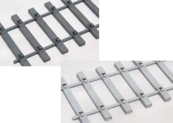
construction of plain track, bases are available for the UK standard
track gauge, in the form of a single plastic moulding containing
several sleepers joined by runners to give the correct standard
sleeper spacing. These are complete with integrally moulded track
fixings and simply require the sliding-in of two lengths of rail to
give effectively a length of flexible track. Some makes can also be
bought ready-assembled.
For the
construction of plain track, bases are available for the UK standard
track gauge, in the form of a single plastic moulding containing
several sleepers joined by runners to give the correct standard
sleeper spacing. These are complete with integrally moulded track
fixings and simply require the sliding-in of two lengths of rail to
give effectively a length of flexible track. Some makes can also be
bought ready-assembled.
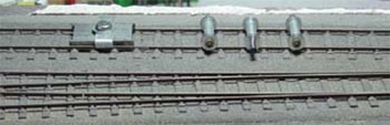
For track with bullhead rails - the traditional track used in the UK until the 1960s - these track bases represent timber sleepers fitted with cast iron S1 type rail chairs suitable for the 1930s onwards. The more recent track with flat bottom rails can be modelled with the alternative concrete sleeper bases moulded with Pandrol track clips.
 For the transition period, eg cast iron chairs on pre-cast
concrete sleepers, or flat bottom rails on timber sleepers the
individual track components described later will have to be used.
For the transition period, eg cast iron chairs on pre-cast
concrete sleepers, or flat bottom rails on timber sleepers the
individual track components described later will have to be used.
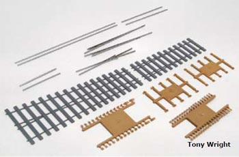
Apart from the limitation of chair type, there are other compromises associated with the production of a one piece plastic moulding for the sleeper and rail fixings - particularly in the representation of the wooden keys used with cast iron rail chairs. This can be overcome by the use of individual components for the sleepers and chairs.
 The chair mouldings hold
the rail in a prototypical manner, with the only soldering being the
attachment of dropper wires to the rail for power supply purposes. The
appropriate number of chairs is threaded on a length of rail and then
fixed in place by gluing the chairs to plastic or plywood sleepers. To
fix the second rail in place, a track gauge is used, thus ensuring
that the rails are spaced the correct distance apart.
The chair mouldings hold
the rail in a prototypical manner, with the only soldering being the
attachment of dropper wires to the rail for power supply purposes. The
appropriate number of chairs is threaded on a length of rail and then
fixed in place by gluing the chairs to plastic or plywood sleepers. To
fix the second rail in place, a track gauge is used, thus ensuring
that the rails are spaced the correct distance apart.
Plastic sleepers are available with raised pips on the sleeper moulding which fit into circular recesses in the base of the chairs. These pips are spaced to suit the UK standard track gauge. The use of these locating pips makes assembly easier and should theoretically allow the track to be built without recourse to a track gauge, but the use of an appropriate track gauge is still recommended.

The use of individual chair mouldings allows for much greater variety, and mouldings are currently available for three-bolt S1, two-bolt GWR, four- bolt MR/LMS and three-bolt LSWR chairs as well as 4 bolt L1 bridge chairs. Individual Pandrol and ST type rail fixings for flat bottom rail are also available.
These individual chairs and fixings can be combined with the different timber or concrete sleeper mouldings to represent a wide range of track types. The chairs can also be glued directly to plywood sleepers using a suitable solvent, but the use of a track gauge is essential if this form of track construction is adopted. Some modellers prefer the appearance and individuality of wooden sleepers which can be coloured and weathered using a variety of stains or paints.
Plywood sleepers are also used in the 'Brook Smith' track system, which was the earliest form of P4 track construction. With this method, the sleepers are pre-punched for special rivets which are set into the plywood and hold the rail at the correct height above the top of the sleeper. For straight bullhead track, the rail is then soldered to the top of the rivet using a track gauge and straight edge.
 A gauge is then be used to set the
second rail at the correct spacing. This results in a very rigid form
of track construction.
A gauge is then be used to set the
second rail at the correct spacing. This results in a very rigid form
of track construction.
For curved track it is normal to solder only one rail to the rivets before the track is curved to suit the intended track plan. This rail should be located on the inside of the curve, and when the second rail is then being set in place a triangular track gauge should be used to introduce a degree of gauge-widening on the curve, in conformance with the prototype.
After the track has been laid, ballasted and tested, cosmetic chairs can be added to complete the scale appearance. Early cosmetic chairs were cast in white metal, and some specialist chairs are still available in that form, but practice today is to use the plastic chairs described above, cut in half and glued on each side of the rail. Although somewhat tedious, if a number of sleepers are detailed every evening the process will be accomplished relatively quickly without becoming too boring!
If you are using the 'Brook Smith' system for flat bottom track construction, then etched baseplates are sandwiched between the rail and track rivet when soldering the rail in place, but using the rivets upside down. When laid using this technique, the rivet heads hold the sleepers above the underlay, and hence a slightly greater depth of ballast is needed.
For those favouring track construction using printed circuit board, fold-up etched chairs are now available, which are designed to be soldered directly to the copper coating on the sleepers. Whilst not being as three dimensional as the moulded chair components, these can be remarkably effective from normal viewing distances.
Someone starting in track construction will find the pre-formed track bases easiest to use, but those with more experience, or of a more adventurous nature, might wish to obtain components covering a selection of these construction methods in order to try them out to see what best suits their skills and interest.
Points and Crossings
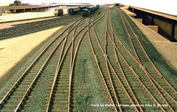
Although a P4 layout could easily be built using plain track only, especially with preformed track bases, it would have little operating potential, and thoughts must inevitably turn to points and crossings. On the prototype, points are not referred to by their radius but by an alpha-numeric code (eg: A7, B6 etc.), in which the letter defines the length of the switches (point blades) and the number defines the crossing angle.
It is the combination of these components which determines the effective radius of the point. These codes are also employed on the different templates (drawings) used in modelling P4 pointwork, and are described later.
Unlike in OO gauge, points are not available as ready-to-lay in P4, and the economics of production means that this situation is unlikely to change in the foreseeable future. All is not doom and gloom, however, as point kits have recently been introduced for bullhead track in which all the rail components are cut accurately to length (and pre-shaped where necessary) with the blades/stock rails and vee/wing rails supplied as pre-assembled units.
Plastic sleeper bases are provided together with plastic mouldings covering all the different chair castings used on the prototype. It is only necessary to thread the chairs on to the rail in the locations shown in the instructions and to glue these to the base moulding to construct the point. No metalworking skill is required, other than the ability to solder dropper wires just as is necessary for plain line. Kits for diamond crossings and single/double slips, are now available, and turnouts for flat bottom track are planned.
 Such convenience does,
however, come at a price and modellers who are able to file their own
point blades and assemble their own vees can produce points costing
little more than the cost of the track components for an equivalent
length of double track covering the length of the point.
Such convenience does,
however, come at a price and modellers who are able to file their own
point blades and assemble their own vees can produce points costing
little more than the cost of the track components for an equivalent
length of double track covering the length of the point.
You can use plastic, printed circuit board or plywood point timbers to match your plain track construction. If you are contemplating building a significant amount of point and crossing work it might be worthwhile buying a set of jigs which simplify filing of the rails for the blades and vees.
All of these methods of track construction, along with prototype information are explained much more fully in the Digests, published by the Scalefour Society.