Unless extreme prototype accuracy bothers you in these matters problems with the minimum switch opening near the heel are very unlikely. I just set the switch opening at the toe close to 1.5mm and let the rest look after itself, I have never seen trouble from that cause, it would have to be significantly less than the check rail gap to affect running.
Whilst the prototype does not like the switches to contact the flange backs due to the potential problems from shaking the detection and drives mentioned by Martin, I have seen a fair number of shiny patches on the backs of switches over the years where such contact was clearly happening.
But IMHO with our models its a non issue, get the switch tips fitting right, the switch opening sufficient, and make sure there is no tight gauge through the switches, all will then be sweet.
Regards
Keith
Turnout troubles...
-
grovenor-2685

- Forum Team
- Posts: 3923
- Joined: Sun Jun 29, 2008 8:02 pm
-
andrew jukes
Re: Turnout troubles...
Expressed differently, Keith, but I think our conclusions are the same.
No, Martin, I haven't (and wouldn't) try nickel silver for other reasons. In any case, scaling means model rail is relatively stiffer than real rail, so choosing a stiffer model option seems counter-intuitive. And I can't work out how the balance between stiffness towards the heel end of the switch rail (bad) and stiffness in the planing (good) works out if a stiffer material is chosen for a model switch rail.
Andrew
-
Martin Wynne

- Posts: 1172
- Joined: Mon May 14, 2012 4:27 pm
Re: Turnout troubles...
andrew jukes wrote:No, Martin, I haven't (and wouldn't) try nickel silver for other reasons. In any case, scaling means model rail is relatively stiffer than real rail, so choosing a stiffer model option seems counter-intuitive.
Hi Andrew,
I wasn't suggesting that you should adopt nickel-silver. Just wondering if the difference between nickel-silver and steel rail accounts for the differences in reported experience.
regards,
Martin.
40+ years developing Templot. Enjoy using Templot? Join Templot Club. Be a Templot supporter.
-
Russ Elliott

- Posts: 930
- Joined: Thu Jun 02, 2011 6:38 pm
Re: Turnout troubles...
Right.
Given that we can ignore any danger to model stretcher bars and detection gear, but bearing in mind the desirability of avoiding contact between the leading edges of the backs of model wheel flanges with switch rails when traversing the diverging path of a turnout (the problem side is invariably on the diverging path, where wheelsets will not be parallel to the gauge), would there be support for typical wheelbases traversing a B-switch for the following recommended dimensions at turnout switches:
I have stated 0.8mm on the assumption that there seems to be general support for 0.1mm of GW straddling the diverging path of a B-switch.
(0.8 = 0.7 + 0.1.)
-
Will L

- Posts: 2528
- Joined: Sun Jul 20, 2008 3:54 pm
Re: Turnout troubles...
Considering the impact of any difference in stiffness between steel and nickel silver rail. I rather doubt it it makes an significant difference to the curves taken up by the switch rail, assuming they are filed to the same shape. What it does is effect the amount of force needed to push the switch over.
Will
Will
-
Martin Wynne
- Posts: 1172
- Joined: Mon May 14, 2012 4:27 pm
Re: Turnout troubles...
Russ Elliott wrote:I have stated 0.8mm on the assumption that there seems to be general support for 0.1mm of GW straddling the diverging path of a B-switch. (0.8 = 0.7 + 0.1.)
Hi Russ,
Not too sure where this "general support" arises or where the 0.1mm comes from rather than a scale 3/4" GW max (0.25mm), or how this gauge dimension is intended to be set? What is the corresponding recommendation for the opposite switch rail? How do these dimensions change for a curved switch?
I wouldn't dispute the usefulness of gauge-widening at the switch heel as shown, but any widening at the end of planing is surely undesirable? It would prevent the straight switch rail from seating correctly against the stock rail. Setting the stock gauge correctly at the end of planing is half the battle in creating a sweet switch.
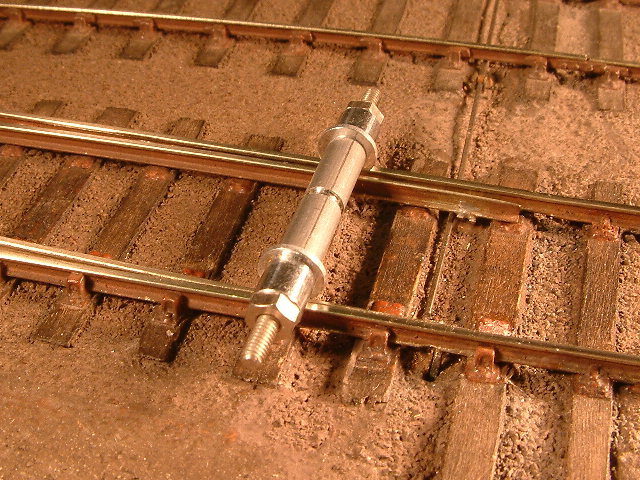
Given that the amount of any widening is a bit unpredictable, a better recommendation would be to test the open switch rail with the CG tool, which can apply to both switch rails and be regardless of any curving of the switch:
regards,
Martin.
You do not have the required permissions to view the files attached to this post.
40+ years developing Templot. Enjoy using Templot? Join Templot Club. Be a Templot supporter.
-
Russ Elliott
- Posts: 930
- Joined: Thu Jun 02, 2011 6:38 pm
Re: Turnout troubles...
Martin Wynne wrote:Not too sure where this "general support" arises or where the 0.1mm comes from rather than a scale 3/4" GW max (0.25mm), or how this gauge dimension is intended to be set?
The +0.1mm TG on this divergent path is intended to convey that a little bit of GW could be desirable at the toe end, in recognition of the effective radii (your 814mm approx for an A-switch, and 1090mm for a B) presented when entering and exiting the switch, and that these radii are within the range where we might normally (in the case of plain track) apply some GW. The 0.1mm GW is a hopeless compromise of course, but in principle, is it really any different to what a joggle provides?
What is the corresponding recommendation for the opposite switch rail?
0.7mm is probably fine for the straight road. The straight road is not the problem one.
How do these dimensions change for a curved switch?
Now that is getting complicated. I'm looking for a reasonably simple exposition, requiring no more than a drillbit or a bit of plasticard.
I wouldn't dispute the usefulness of gauge-widening at the switch heel as shown, but any widening at the end of planing is surely undesirable? It would prevent the straight switch rail from seating correctly against the stock rail.
I take your point in respect of the end of planing (are we talking about the same 'end'?), but I don't see how the seating of the straight switch rail would be compromised.
Your CG test on the open switch rail is a very thorough approach, but my worry is that it gives the impression that an unspecified length of the open rail should be set at CGmax, which promotes the idea of that open rail acting with a proper checking function, which is exactly the opposite of what we want. Our objective here is to prevent flangebacks from touching that open rail.
-
Martin Wynne
- Posts: 1172
- Joined: Mon May 14, 2012 4:27 pm
Re: Turnout troubles...
Russ Elliott wrote:The 0.1mm GW is a hopeless compromise of course, but in principle, is it really any different to what a joggle provides?
Hi Russ,
It's entirely different because for a joggle the blade planing is modified to match -- the tip is 3/8" thick instead of a knife edge.
The "end-of-planing" EP is the position where the planing runs out and the rails begin to diverge (C in the diagrams below). The gauge between the stock rails at this point is called the "stock gauge" (sg in the lower diagram below) and it must be exactly one rail-width greater than the track gauge, no gauge-widening can be permitted. Otherwise the straight switch blade cannot seat correctly against the curved stock rail, this is true for joggled or unjoggled switches:
undercut/unjoggled:
straightcut/joggled:
stock gauge:
If you want to have gauge-widening through a switch, really the only way is to gauge-widen the whole switch in the American prototype fashion, i.e. build the whole thing to say 19.0mm gauge for both roads. The gauge is progressively widened in the switch front section between the rail joint and the switch toe, and then for the main road progressively reduced back to standard gauge beyond the switch heel. The turnout road can continue at the wider gauge, or widen further beyond the switch heel.
More at: http://www.templot.com/martweb/gs_realtrack.htm#set
regards,
Martin.
40+ years developing Templot. Enjoy using Templot? Join Templot Club. Be a Templot supporter.
-
andrew jukes
Re: Turnout troubles...
Martin Wynne wrote:
If you want to have gauge-widening through a switch, really the only way is to gauge-widen the whole switch in the American prototype fashion, i.e. build the whole thing to say 19.0mm gauge for both roads. The gauge is progressively widened in the switch front section between the rail joint and the switch toe, and then for the main road progressively reduced back to standard gauge beyond the switch heel. The turnout road can continue at the wider gauge, or widen further beyond the switch heel.
That's pretty much what I do. Seems I'm an American!
Of course, my aim is primarily to ensure there is no under-gauge track in this critical area.
Andrew
Return to “Track and Turnouts”
Who is online
Users browsing this forum: ClaudeBot and 0 guests