Navigation Sidings

Sub-forum for the layouts....
User avatar
Martin Wynne
Posts: 1174
Joined: Mon May 14, 2012 4:27 pm

Re: Navigation Sidings

Postby Martin Wynne » Wed Oct 25, 2023 2:44 pm

.
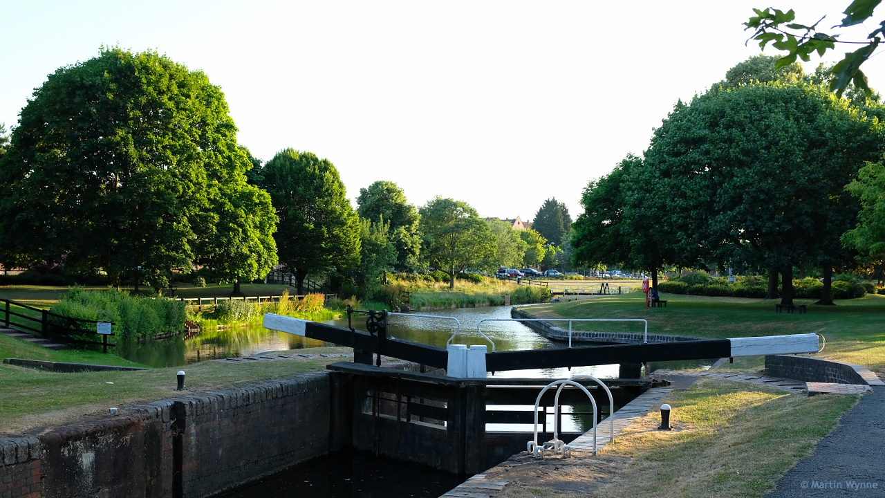
This lock originally had 4 gates at each end, so that it could go up or down:

Image

The sockets for attaching another gate can still be seen in front of the ladder hoops. It links the Droitwich Barge Canal to the the canalized River Salwarpe, which could at times be higher or lower than the level in the Barge Canal.

Martin.
40+ years developing Templot. Enjoy using Templot? Join Templot Club. Be a Templot supporter.

Jeremy Good
Posts: 280
Joined: Fri Feb 19, 2010 10:36 pm

Re: Navigation Sidings

Postby Jeremy Good » Wed Oct 25, 2023 3:05 pm

James,

Good to see this proposal taking shape.

If nothing else, it should give Me Tatlow something to think about when he is checking it fits inside the size parameters! I’m sure with his years of professional experience he’ll be able to measure it ok!!

Jeremy

James Walters
Posts: 70
Joined: Sun Jul 11, 2021 12:16 pm

Re: Navigation Sidings

Postby James Walters » Wed Oct 25, 2023 3:39 pm

The baseboard plan calculates out at 18.74 sq.ft. although there will be a small non-scenic area of just less than 1 sq.ft.
:)

Layout size.JPG
You do not have the required permissions to view the files attached to this post.

Jeremy Good
Posts: 280
Joined: Fri Feb 19, 2010 10:36 pm

Re: Navigation Sidings

Postby Jeremy Good » Wed Oct 25, 2023 4:00 pm

Don’t make it too easy for Mr T to check…

I really like the concept and plan - it was always one of my favourites from that one of Mr Rice’s treatise on layout design. Your changes should make it an attractive model.

Good luck.

Jeremy

MikeAllerton
Posts: 28
Joined: Sun Oct 10, 2021 7:43 pm

Re: Navigation Sidings

Postby MikeAllerton » Wed Oct 25, 2023 4:04 pm

Martin Wynne wrote:.
This lock originally had 4 gates at each end, so that it could go up or down:

Image

The sockets for attaching another gate can still be seen in front of the ladder hoops. It links the Droitwich Barge Canal to the the canalized River Salwarpe, which could at times be higher or lower than the level in the Barge Canal.

Martin.


The slots aren't for a second set of gates, they're for stop planks used to retain the water in the upper section of canal, whilst the lock is being repaired. Also necessary if the canal is breached below the lock for the same reason.

Mike

User avatar
Martin Wynne
Posts: 1174
Joined: Mon May 14, 2012 4:27 pm

Re: Navigation Sidings

Postby Martin Wynne » Wed Oct 25, 2023 4:24 pm

MikeAllerton wrote:The slots aren't for a second set of gates, they're for stop planks used to retain the water in the upper section of canal, whilst the lock is being repaired. Also necessary if the canal is breached below the lock for the same reason.

Hi Mike,

I didn't mention the slots. I was referring to the hinge sockets for the second set of gates, which you can see painted white next to the ladder hoop.

Here is the 1901 25" map, showing all four sets of gates, and the swing bridge across the lock (behind the camera):

barge_canal_lock.png

cheers,

Martin.
You do not have the required permissions to view the files attached to this post.
40+ years developing Templot. Enjoy using Templot? Join Templot Club. Be a Templot supporter.

MikeAllerton
Posts: 28
Joined: Sun Oct 10, 2021 7:43 pm

Re: Navigation Sidings

Postby MikeAllerton » Wed Oct 25, 2023 5:59 pm

My mistake, apologies Martin

bécasse
Posts: 377
Joined: Sun Jun 17, 2018 8:26 am

Re: Navigation Sidings

Postby bécasse » Thu Oct 26, 2023 11:25 am

If you do opt for the "green diesel" era, consider modelling the canal as disused. Disused canals are rarely featured on model railway layouts - although Pendon has one (a historically correct feature of The Vale) - but can actually be a far more attractive scenic feature than one that is still in use.

Although this website http://www.penninewaterways.co.uk/restoration.htm is principally about the restoration of various Pennine canals it does include some atmospheric "before" shots (look at the Huddersfield Narrow Canal for example) which might provide much inspiration.

James Walters
Posts: 70
Joined: Sun Jul 11, 2021 12:16 pm

Re: Navigation Sidings

Postby James Walters » Thu Feb 15, 2024 7:26 pm

So after some months of going back and forth with my design intentions, I have now settled on the final track plan, (I think).
I thought it also time to update what has been going on.

As a reminder, this project started as an interpretation Iain Rice's Navigation Sidings, but has I'm afraid morphed somewhat. However, it has now settled upon what I think might make for a more interesting layout operation-wise. Not everyone's cup of tea perhaps, but what is?

Before I show the revised plan, I will first clarify the question of era and location. This will still be set in the West Yorkshire area, as a fictitious addition to the Midland's proposed West Riding extension between Dewsbury and Bradford. I had toyed between steam and green diesel as the era, but this has now been settled upon as Johnson era steam. I couldn't resist the offer from an area group colleague Greg, who offered to help out with some rolling stock and loco's. Greg is a steam man, and I think like me not a huge fan of post Johnson Midland locos. This settles the operational era debate, Midland pre-1907!

So here's the plan from Templot, I'll update this with all the scenic stuff in time:
v27_2.png


Given that there will be Johnson loco's, it seemed a shame not to have a passenger service, so there will be a platform between the the top-most tracks of the plan, the bay platform allowing for another company's stock to work the station. This was Greg's idea, and a good one in that it will allow for some operational variety. Space is obviously at a premium given the challenge rules, so the platform and run around roads are connected via the turntable. I struggled to find an appropriate Midland prototype for this, so have based the concept upon the LNWR station at Harbourne.

harborne_station_turntable_7_5_29_cc-jc-williams.jpg

Image copyright CJ Williams and http://www.disused-stations.org.uk, used with permission

The remaining tracks connected to the 'main line' serve a basic wagon sorting purpose.
The lower line shown on the plan, is at a lower level and will arrive from a local limestone quarry (off-scene). At the far right-hand side of the layout a wagon lift will exchange full and empty wagons between the levels. This should allow a wide variety of goods to be moved in and out of the location.
The area just below the tracks as we look at the plan will be the canal basin.

Here's another view, showing the extent of the baseboards. The fiddle yard will be on the left.

V27_2 Baseboard Plan.jpg


Clearly, the thinking has moved on somewhat from the original plan. I think therefore I ought to change the name, Navigation Basin seems perhaps appropriate. The changes also mean that I need to name the station...suggestions on a post card please.

Now then, one of my reasons for entering the challenge was to experiment with Martin's excellent Plug Track in a meaningful way.
And here's the progress:

Box of Track Panels.jpg

All of the track panels for the upper level with the exception of the double-slip are now complete, and most have been stained and chaired.

I've laser cut some cardboard mock-ups for the baseboards using some old boxes:

Card mock up.jpg


And tested that the track panels actually fit...
Track Panels laid out 2.jpg

Track Panels laid out 2.jpg


I'm really pleased with the Plug Track chairs. I've chosen to use the loose outer jaw option, and I'll fit the rail once the timbering bases have been fitted to the baseboards.

Chairing.jpg

Yes, I know these are REA chairs and not suitable for a Midland line c.1900. I could of course create my own Midland chairs and plug them in, but that would defeat the object of showing what can be done with Templot alone. Should Martin ever create Midland chairs, I could very simply pop these chairs out and swap them over. But, given that this is all a figment of imagination, does it really matter?
I of course know the answer to this question, but I suspect that the chairs will be the least of my crimes to prototype practice. :)

Finally, I wanted a nod to Martin's 85A domain, and have selected Evesham station building as a suitable prototype for my own. I'm yet to decide upon brick or stone for it, hopefully the end result wont offend too much.

Further updates to follow sporadically as progress is made. :)
You do not have the required permissions to view the files attached to this post.
User avatar
steamraiser
Posts: 562
Joined: Thu Dec 31, 2009 4:49 pm

Re: Navigation Sidings

Postby steamraiser » Thu Feb 15, 2024 8:39 pm

Have you tried operating your layout on paper or in your mind?
Train arrives from off scene, drops the guards van off, then the wagons.
How does the guards van and various wagons end up at the opposite end of the loco ready to depart?

Gordon A

James Walters
Posts: 70
Joined: Sun Jul 11, 2021 12:16 pm

Re: Navigation Sidings

Postby James Walters » Thu Feb 15, 2024 9:06 pm

Hi Gordon,
A good question.
This is what I had in mind. Am I missing something?
Operation diagram.jpg


Apologies for the rather basic drawing, it's a lot better than the scraps of paper on my workbench though. :)
You do not have the required permissions to view the files attached to this post.


Return to “Challenge Layouts”

Who is online

Users browsing this forum: ClaudeBot and 1 guest