Here it is, my first Jubilee Challenge post.
For my entry I am visiting an Iain Rice classic – Navigation Sidings, albeit with modifications to improve the operating potential. Yes, I know it is not the most realistic of concepts, and some of the curves will be mighty-tighty, but it crams so much into a small space, with plenty of aesthetic appeal.
My only hope is that it will be fun to build and joyful to behold.
Readers of this forum may be familiar with my ongoing project to build Bexhill West. Having already re-started that project once in a move from OO to P4, and with an anticipated completion date of sometime later this decade (hopefully), folks might be curious as to why I might divert energy and enthusiasm into a challenge layout?
This is a good question - without a simple answer, but let me try...
Firstly, I would like to get something complete and run-able in a realistic period, it would be good for my motivation and also create occasional content for my YouTube channel.
Secondly, I would like to build a layout using Martin Wynne's excellent plug track system.
I have been enjoying experimenting with Plug Track, and there really is no better way to learn how to do something than to have an actual use for it.
Maybe, my experiences with Plug Track might encourage others to try it for themselves.
Finally, I cannot remember when I first saw Iain Rice's plan for Navigation Sidings, but it seems to have popped-up here and there, each time leaving an impression upon me.
Bexhill West will be many more years in the making, and I am in no rush with that project as I am trying to get it 'all right'.
Navigation Sidings will be an opportunity for folly, and allow me to tackle architectural modelling projects which I would otherwise not have the opportunity to try. It is my ambition that this forum thread might be fun to work on as well. I hope visitors to the thread might enjoy sharing their expertise and own sense of fun as the project develops.
I have attached a draft layout plan to give an impression of the proposal, although I will no-doubt make modifications here and there to suit my whims.
My best wishes,
James
Updates and back story to follow….
Navigation Sidings
-
James Walters
- Posts: 70
- Joined: Sun Jul 11, 2021 12:16 pm
Navigation Sidings
You do not have the required permissions to view the files attached to this post.
-
Worzels Works
- Posts: 76
- Joined: Tue Jun 20, 2023 4:04 am
Re: Navigation Sidings
I'm very glad to see you building this James! looking forward to seeing progress and I'm sure it'll end up looking great, always loved the idea of the amount of vertical separation and urban grubbiness you could achieve with Navigation Sidings.
EDIT: the only comment I will make is be sure to have a look at the towpath bridge on the drawing, I'm sure it was just to represent it on the rice plan but tow path bridges should have a loop for the tow horse to remain on the same end (up/down) of the bridge before passing back under on the opposite side of the canal. (to avoid having to un-tie the horse at every bridge) that might be a poor explanation but hopefully these pics explain better!


Both Images from Core77.com showing bridges 77 and 79 on the Macclesfield canal, although apologies if you were already aware of this!
p.s. don't mind me hoping you do ambient sound so I can sit watching and listening to the 'put put' of a lister powered barge...
EDIT: the only comment I will make is be sure to have a look at the towpath bridge on the drawing, I'm sure it was just to represent it on the rice plan but tow path bridges should have a loop for the tow horse to remain on the same end (up/down) of the bridge before passing back under on the opposite side of the canal. (to avoid having to un-tie the horse at every bridge) that might be a poor explanation but hopefully these pics explain better!
Both Images from Core77.com showing bridges 77 and 79 on the Macclesfield canal, although apologies if you were already aware of this!
p.s. don't mind me hoping you do ambient sound so I can sit watching and listening to the 'put put' of a lister powered barge...
Yours aye,
James
James
-
steamraiser
- Posts: 562
- Joined: Thu Dec 31, 2009 4:49 pm
Re: Navigation Sidings
How is it intended to operate the layout?
Will the lack of a run round loop allow this?
Will the lack of a run round loop allow this?
-
davebradwell
- Posts: 1185
- Joined: Fri Jan 18, 2019 3:48 pm
Re: Navigation Sidings
You might be able to swap elements of the canal around to improve things - there's no-where to tie-up anywhere near the pub, for example, although its position between road and canal is perfect. There's an awkward turn below the lock and the far wall would have lumps knocked out of it and long bits of rail bolted on to fight off boats. I'm trying to remember a bridge - it might have been on the Macclesfield - where the bridge wall just flowed round elegantly to become the wall of the pub. Best pint of Pedigree ever but it was a long time ago.
On further inspection, perhaps it's best not to be too pedantic and just go for appearance!
DaveB
On further inspection, perhaps it's best not to be too pedantic and just go for appearance!
DaveB
-
Tim V

- Posts: 2875
- Joined: Tue Jul 29, 2008 4:40 pm
Re: Navigation Sidings
Canal tow-paths are almost always on the valley (lower) side of the canal. They only swapped sides when the canal crossed from one side of the valley to the other. They were easier to build that way.
In the case of the plan, as the railway is on a higher level, I see no obvious reason for the tow-path to swap sides. If you leave the tow-path on the near side, there could be a wharf by the pub.
In the case of the plan, as the railway is on a higher level, I see no obvious reason for the tow-path to swap sides. If you leave the tow-path on the near side, there could be a wharf by the pub.
Tim V
(Not all railways in Somerset went to Dorset)
(Not all railways in Somerset went to Dorset)
-
Worzels Works
- Posts: 76
- Joined: Tue Jun 20, 2023 4:04 am
Re: Navigation Sidings
davebradwell wrote:On further inspection, perhaps it's best not to be too pedantic and just go for appearance!
For the record I completely agree with Dave
Yours aye,
James
James
-
James Walters
- Posts: 70
- Joined: Sun Jul 11, 2021 12:16 pm
Re: Navigation Sidings
Thank you gents for your interest thus far.
James, thank you for the bridge reference photos. They are a great reference I had something similar in mind, although DaveB's suggestion of the bridge flowing into the pub wall sounds interesting. I shall scour the Macceslfield on Google Earth to see if I can find it.
With regard to operation, the plan is that the siding from the tandem turnout, labelled 'to possible extension' would be serving an off-scene industrial works of some description, (possibly Gypsum related). Loaded wagons would be bought down to the sidings from the industry, sorted into rakes for dispatch. Empties would be bought in from the RH fiddle yard, to be shunted up to the works.
Thus the loaded and empty wagons will be cycled repeatedly between the fiddle yard roads.
The LH fiddle yard would effectively be a simple head shunt to allow a reasonable rake of empties to be bought 'up' from the RH fiddle yard, and backed into the sidings.
By altering the track plan to include the LH fiddle road, there is scope for some interesting through traffic to brighten up what might be an otherwise dull operating schedule.
I have in mind one other feature which should significantly improve operational interest, but I need to see if it will work first before I reveal what it is.
-
James Walters
- Posts: 70
- Joined: Sun Jul 11, 2021 12:16 pm
Re: Navigation Sidings
davebradwell wrote:
On further inspection, perhaps it's best not to be too pedantic and just go for appearance!
DaveB
That's the plan. I spend far too much time deliberating detail with Bexhill West, this is will be purely for fun.
-
davebradwell
- Posts: 1185
- Joined: Fri Jan 18, 2019 3:48 pm
Re: Navigation Sidings
Yes, I found I was rapidly digging myself into a hole as the canal features don't add up. Will look nice, though.
DaveB
DaveB
-
Worzels Works
- Posts: 76
- Joined: Tue Jun 20, 2023 4:04 am
Re: Navigation Sidings
Glad to hear you're keeping the original operating idea too James, will make for a good challenge shunting a long train over that point work.
Also going to heed Dave's advice again and not get too deep into canal features!
Also going to heed Dave's advice again and not get too deep into canal features!
Yours aye,
James
James
-
davebradwell
- Posts: 1185
- Joined: Fri Jan 18, 2019 3:48 pm
Re: Navigation Sidings
You'd be wise to research a few basics, though and get the shape/style and fittings of the lock correct for your part of the world to save an ear bashing at exhibitions. It would likely have a dreaded short balance beam just to show you cared. The sides of the cut wouldn't be too parallel in such a setting so plenty of scope for artistic flair.
DaveB
DaveB
-
Noel

- Posts: 1988
- Joined: Wed Jun 23, 2010 1:04 pm
Re: Navigation Sidings
davebradwell wrote:Yes, I found I was rapidly digging myself into a hole as the canal features don't add up.
Indeed. There are one or two issues on the railway side as well as James seems to have discovered...
davebradwell wrote:You'd be wise to research a few basics, though and get the shape/style and fittings of the lock correct for your part of the world to save an ear bashing at exhibitions.
It will take a bit more than that, I think, as this canal would, in reality, have been somewhere between very difficult and impossible to operate.
The original plan was published in "An Approach to Model Railway Layout Design - Finescale in Small Spaces" in 1990. I don't think it's one of his best designs, but it is nevertheless one of several in the book which has made me think seriously about what I want from a layout...
Regards
Noel
Noel
-
Tim V
- Posts: 2875
- Joined: Tue Jul 29, 2008 4:40 pm
Re: Navigation Sidings
A certain modeller who will remain nameless built a model based in Yorkshire, but modelled a lock from the Oxford Canal! That raised a few eyebrows.
Tim V
(Not all railways in Somerset went to Dorset)
(Not all railways in Somerset went to Dorset)
-
James Walters
- Posts: 70
- Joined: Sun Jul 11, 2021 12:16 pm
Re: Navigation Sidings
The layout will be set in West Yorkshire, and there will be canal influences from the Leeds & Liverpool canal, although the lock will be based upon an example from the Calder & Hebble canal.
It will have to be 60 ft max length lock to stand any chance of fitting in the space available.
For the architecture on the layout I will take inspiration from my favourites in the Hebden Bridge area. Beyond that, it will all be artistic licence and selective compression. The ‘actual’ location will be suitably vague, although there is a back-story to its existence which I will share in due course.
-
bécasse
- Posts: 377
- Joined: Sun Jun 17, 2018 8:26 am
Re: Navigation Sidings
Tim V wrote:A certain modeller who will remain nameless built a model based in Yorkshire, but modelled a lock from the Oxford Canal! That raised a few eyebrows.
Doubtless because Oxford Canal locks are distinctive in (mostly) having single gates at both ends of the lock (hence much easier to model). There was also a period post-WWII when some these gates were fitted with rather distinctive steel arms, although I think that most, if not all, have now reverted to the traditional tapering wooden ones. Another oddity of the Oxford where it shares its course with the River Cherwell is several "coffin" shaped locks intended to maximise the amount of water extracted from the river each time the lock is used.
-
Martin Wynne

- Posts: 1174
- Joined: Mon May 14, 2012 4:27 pm
Re: Navigation Sidings
James Walters wrote:The layout will be set in West Yorkshire ... ...The ‘actual’ location will be suitably vague
Hi James,
If it's a fictional canal company, who knows, they may have used the Buck patent geared horizontal paddles. Until now thought to have been used only on the Monty, but there are rumours of recently discovered examples at a secret location in West Yorkshire...
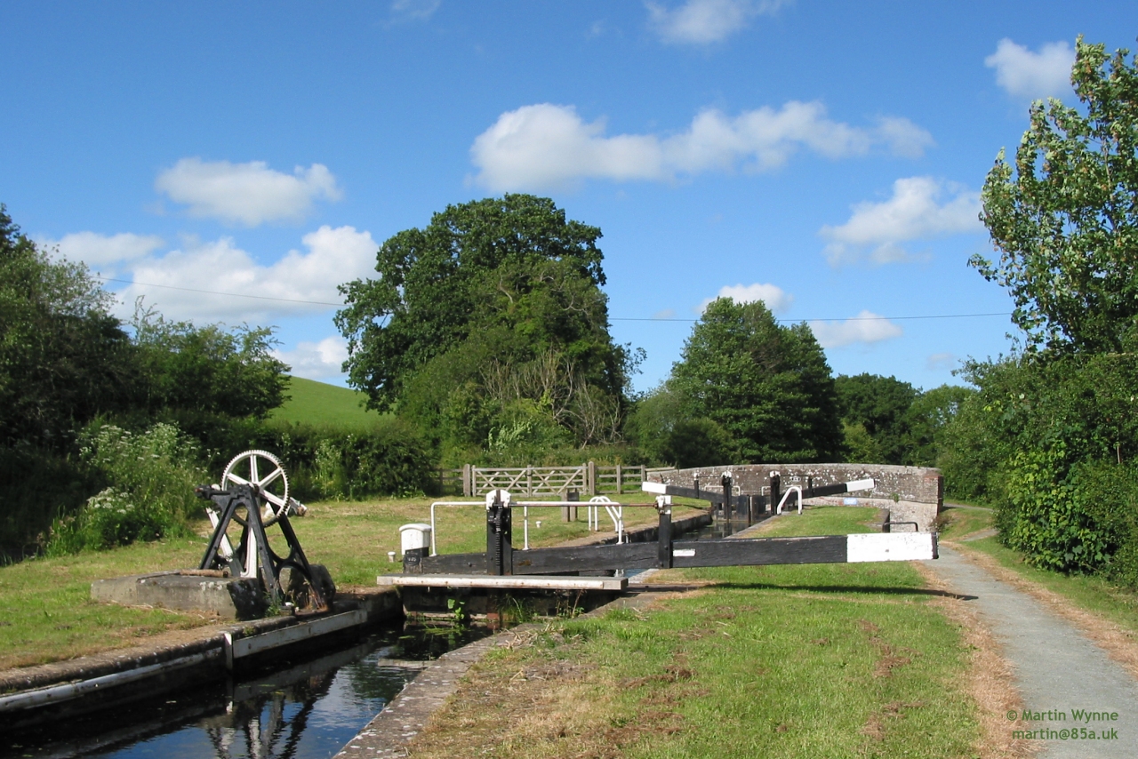

I have never seen them modelled.
cheers,
Martin.
40+ years developing Templot. Enjoy using Templot? Join Templot Club. Be a Templot supporter.
-
James Walters
- Posts: 70
- Joined: Sun Jul 11, 2021 12:16 pm
Re: Navigation Sidings
Thanks Martin,
As it happens, I found this in the long-lost archives of the West Riding Canal Company....
As it happens, I found this in the long-lost archives of the West Riding Canal Company....
You do not have the required permissions to view the files attached to this post.
-
Martin Wynne
- Posts: 1174
- Joined: Mon May 14, 2012 4:27 pm
Re: Navigation Sidings
+1
40+ years developing Templot. Enjoy using Templot? Join Templot Club. Be a Templot supporter.
-
Mark Forrest
- Posts: 49
- Joined: Mon Nov 28, 2011 6:44 pm
Re: Navigation Sidings
This is a plan I've looked at many times, I look forward to seeing your progress with this project.
-
david_g
- Posts: 19
- Joined: Sun Nov 27, 2011 9:05 pm
Re: Navigation Sidings
[quote="Worzels Works"
p.s. don't mind me hoping you do ambient sound so I can sit watching and listening to the 'put put' of a lister powered barge...[/quote]
Bolinder surely:
https://www.youtube.com/watch?v=C-1GxOJ2Q2A
(I think they're the work of the devil myself, give me proper twin diesel any day )
)
p.s. don't mind me hoping you do ambient sound so I can sit watching and listening to the 'put put' of a lister powered barge...
Bolinder surely:
https://www.youtube.com/watch?v=C-1GxOJ2Q2A
(I think they're the work of the devil myself, give me proper twin diesel any day
-
James Walters
- Posts: 70
- Joined: Sun Jul 11, 2021 12:16 pm
Re: Navigation Sidings
An update…
I make no excuse for the fact that my challenge entry is based upon my desire to build a model of a bridge. And in particular, a bridge from the West Riding line from Royston to Saville Town. There are two bridges which take my fancy, one over the Calder and Hebble navigation, an impressive three arch stone affair (which still stands) or the now long-since gone truss style bridge which crossed the L&Y line at Headfield Road. I’ve original drawings for both and am keen to have an excuse to build at least one of them.
So, the back story to the project proposes that the Midland Railway did indeed extend from Dewsbury to Bradford, and that Navigation Sidings existed at some point along the route. Exactly where is anyone’s guess. If one is happy to accept this ’fake-news’, then perhaps your imagination will oblige to consider that the route was built as single-line, essentially for the transport of goods, although a minimal passenger service was provided. Mindful of costs, it is supposed that although the route was built as single-track, key infrastructure was built to accept a future double-line expansion should traffic warrant it.
Of course, history tells us that there was never such a demand, but at the point whereby the route was first discussed there was sufficient residual railway-mania to, I believe, make this notion semi-plausible.
Serendipitously, the tunnel built to accommodate the approach from Dewsbury was built double tracked, as was the bridge, which leads off towards Bradford. As such, the second line through the tunnel could connect with some local industry (TBC), and the ‘spare’ track over the bridge could become a useful head shunt for the sidings whereby the industry could store & sort their wagons for dispatch.
And so, the fantasy provides the best (or worst) of both worlds; an unrealistic industrial spur through an expensive tunnel, and an unrealistic head shunt across an excessive bridge/viaduct. With the benefit, that if I change my mind (which is likely), I can pretend it was a double tracked mainline all along.
As a reminder, here’s the original Iain Rice plan…
And here are my modifications (thus far)…
It will be seen that I have double tracked the principal line, but as with my description above it is only the topmost line on the plan which is a through route.
I’ve had to jig the track plan significantly to achieve reasonable curves, and the sidings themselves are yet to be finalized. I suspect that I may reduce them somewhat.
So looking at the plan from top to bottom, there will be low relief warehouses at the backscene, and the line rises from left to right up a steep gradient. I’ve initially drawn this at 1:40, which is extreme I know, but there was a section at this gradient leading into Saville Town goods depot. So it isn’t without prototype, although I suspect I’ll change it to something like 1:80. The area to the left of the portal will feature a mill building based upon a prototype in Hebden Bridge.
The line will exit to the left over one of the bridges described earlier, rather than the two smaller bridges shown on the original plan. Moving on, the sidings themselves will sit atop a stone arch retaining wall. The ‘landscape’ will then drop to a road gently sloping from right to left. The final level will be the canal, lock and basin. Again, I’ve modified the original plan to make the canal slightly more navigable and extended the basin.
The following couple of images show a first mock-up of how all of this might look. I’m currently thinking that the stone arch retaining walls are too high, so I will likely drop these a little, at which point the old Headfield Road bridge would I think be more suitable than the three arch bridge shown here.
As for the period I intend to model… I’ve not decided yet, it was going to be pre-grouping, but I have itch for green diesel as a change from my current project.
You do not have the required permissions to view the files attached to this post.
-
davebradwell
- Posts: 1185
- Joined: Fri Jan 18, 2019 3:48 pm
Re: Navigation Sidings
As the landscape is rising to the right, would it make more sense for the canal lock to do the same? Reduces your tall walls.....or perhaps I've missed something.
DaveB
DaveB
-
James Walters
- Posts: 70
- Joined: Sun Jul 11, 2021 12:16 pm
Re: Navigation Sidings
davebradwell wrote:As the landscape is rising to the right, would it make more sense for the canal lock to do the same? Reduces your tall walls.....or perhaps I've missed something.
DaveB
Hmm, I've debated this myself. I came to the conclusion that the canal rising in contrast to the falling landscape would make the scene more interesting visually. and help balance the overall vista.
That said, you're right, the canal rising to the right would be more realistic. I'll be experimenting with this back and forth no doubt over the coming months. I'll make a little scale model of each concept and take it from there. Thank you for the suggestion.
-
Martin Wynne
- Posts: 1174
- Joined: Mon May 14, 2012 4:27 pm
Re: Navigation Sidings
James Walters wrote:That said, you're right, the canal rising to the right would be more realistic.
Hi James,
I'm not sure I agree about that. The blind viaduct / retaining wall on the right is allowing the railway to follow the hillside, while the canal drops into the valley where the industry is likely to be.
A blind viaduct is used to carry a railway along a rocky hillside. The excavated rock can be used in building blind arches below it to widen the ledge. This reduces amount of material needed to be excavated. A well-known example is the former Merthyr, Tredegar and Abergavenny Railway route through the Clydach Gorge. Now a fine walking/cycling route:

© linked from gwentheritage.org.uk

© linked from railwaypaths.org.uk
Martin.
40+ years developing Templot. Enjoy using Templot? Join Templot Club. Be a Templot supporter.
-
davebradwell
- Posts: 1185
- Joined: Fri Jan 18, 2019 3:48 pm
Re: Navigation Sidings
If you can't make up your mind, you might have one of those irritating stop-locks with a 6" drop, perhaps with a swing bridge across for access just to compound the delay. I also wondered about a lock under the bridge arch to avoid the sight of water flowing off the rear of the baseboard but think you have that well hidden by the bridge.
DaveB
DaveB
Who is online
Users browsing this forum: ClaudeBot and 2 guests